If you’ve never heard the Stebel Nautilus horn in person, it’s difficult to describe. “Loud” is insufficient. Sure it is loud – very loud at 148 db. The two-note tone created by the Nautilus could better be described as “piercing” or even “pseudo-deaffoning.” Both are great qualities in a scooter horn. If you’re looking for a great way to get that absent-minded cager’s attention, look no further. You’re likely to startle the cell phone right out of their hand.
Installing the Stebel Nautilus seems like a complex operation at first. It’s less complex the second time. But now that I’ve done three of these, I think I’ve got it figured out. If you try to look at all of it at once, it seems really daunting. If you break up the install into its basic tasks, it’s actually really easy, especially in the Blur.
There are two basic parts to getting the horn in:
1. Mounting the horn and the relay
2. Wiring the horn and the relay
Supplies
- 6-8 ft of 14-guage red wire. 3 ft of 14-guage black wire
- One in-line fuse holder, also 14 guage, and some 20-amp fuses (I recommend the “blade” type automotive fuses)
- Four slide-type 14-guage crimp connectors (the kind that will fit the blade terminals on the horn and the relay)
- Two ring-type 14-guage crimp connectors (the kind that you can pass a bolt through)
- One 14-gauge junction connector (basically a tube for connecting two wires together)
- One 1/4″ diameter bolt, 1″ long, and a nut.
Tools
- Regular metric socket wrench set with 8mm-12mm sockets and extensions
- Medium size phillips (+) screwdriver
- Crimping tool (you can buy the crimping tool as part of a kit that will have all the connectors you need also)
- Drill with 1/4″ and 5/16″ drill bits
- Multi-meter (voltmeter you can use to test continuity)
Mounting
Believe it or not, mounting one of these horns in a scooter is actually harder than doing the wiring work. It’s five times the size of the OEM horn, so cramming it into the space can be a bit sketchy depending on the scooter. In the Buddy, for example, it’s a total cram job. You’ve got to basically wedge it in there between the frame pieces and strap it down – and that’s after you’ve relocated some of the OEM electronic components. On the Blur, however, all we need to do is drill a hole in the OEM mount and we’re good to go. So let’s get started.
1. Disconnect the Battery.
Open your under-seat storage compartment. The battery is under a tabbed battery compartment cover just aft of the pet carrier bucket. Remove the compartment cover, then remove the two screws on either side of the battery cover itself. Now unscrew the negative (-) battery terminal and push the wire away from the post so that it can’t flop back and touch the terminal again.
2. Remove the horn cover
At the nose of the Blur, there is a black, triangular panel above the headlights and below the headset. It’s got the Genuine G logo in the center of it. That’s the horn cover. It’s attached from behind via two screws in the upper corners and then by a series of clip tabs around its perimeter. Remove the two screws, then gently pry up on those loose corners and work your way down to the big tab at the bottom point of the triangle. It’s pretty sturdy, so don’t worry too much about breaking it. You shouldn’t need anything but your fingers to get it loose.
3. Remove the OEM horn and bracket
With the horn cover removed, you should be able to see the black, circular, OEM horn. It’ll have two wires coming out of it, one green with a yellow stripe, the other black. Disconnect these and lay the wires aside. Be careful to pull on the connecters and not the wires – you don’t want to break these as you’ll need them later. Using a 12mm socket, remove the horn bracket (the horn will come with it). Save the bolt, as we’ll reuse this whole bracket assembly later on. Now grab an 8mm socket and remove the OEM horn from the bracket.
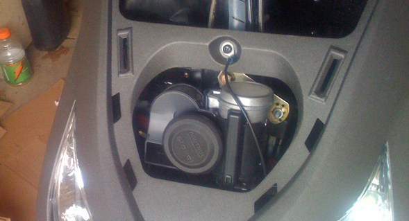
4. Mount the Nautilus and its relay on the OEM bracket.
We’re going to reuse the OEM bracket and OEM mounting point on the Blur’s frame to mount the new horn. We’re also going to use the bracket to mount the relay. Using a 5/16″ drill bit, drill a hole in the center of the OEM bracket (it’s best to start small and work your way up to 5/16″). We’re going to use the bolt/nut that came with the Nautilus to mount it to the bracket in this new hole, then use the original bolt and bracket hole to bolt the bracket back onto the bike. We’ll then use the 1/4″ hole on the end of the OEM bracket (where the old horn used to be mounted) as the mounting point for the relay. Use just a 1/4″ nut/bolt to secure the relay, but you’ll need to drill out the mounting hole on the tab to 1/4″ first. Get everything finger-tight for now. Test mount the new horn and relay and adjust your angles so that you’re not hitting anything. You can do all of this through the horn cover opening, there’s no need to remove the whole nose panel. Do a test fit, and then go ahead and pull the horn back out. We’ll get it all wired up, then mount it for good.
 Wiring
This is actually easier than it seems at first. What you’re essentially doing is creating a new circuit off the (+) side of the battery, running it through the new horn via the relay, and then back to ground. You then use the OEM wires from the original horn to activate the relay. So if you think of this as two separate circuits, it helps keep things more simple. Also, if you have a multi-meter, it’s a very good idea to check the continuity of your wires as you make them, that way if something doesn’t work later in the process, you’ll know you at least have good wires.
1. Tying in to the battery for power
Using a ring connector and your in-line fuse holder, create a patch wire to attach to the (+) battery terminal. Then splice the other end of that fuse holder to a 6′ long piece of red 14-guage wire. You’re going to then feed that wire through the frame. Install a fuse and check for continuity. Then remove the fuse for now – we don’t want anything touching the frame and blowing your main fuse.
2. Feeding the wire through the frame
Since the battery negative (-) is grounded to the frame, we only need to run a positive (+) wire forward to the horn. The easiest way to do this is to remove the “seat bucket” – the pet carrier and actual seat. It’s held in using simply four 10mm bolts – two in the floor of the pet carrier and two in the rear by the battery. When lifting out the assembly, be sure to pause and disconnect the light on the right side. Now you should be able to feed the wire out of the battery box, down the right side of the bike frame and attach it with cable ties as you go. The tricky part will be getting the wire up through the front fork area and into the compartment where the horn is. A wire hanger will work well for this, as you can push it through, tie/tape/bend the electrical wire to it, and then pull it back through. Just be careful that you don’t snag other important wires along the way. Also be sure to turn the handle bars back and forth to make sure nothing is binding. It’s easy and appropriate to follow and even attach to the wiring bundle that already exists in this area. Secure everything, leaving some slack on both ends, and leaving at least 12-18″ of extra wire out the front of the bike.
3. Understanding the wiring
If you’ve never done anything like this before, the whole concept of the relay and the extra wiring probably seems really complex and daunting. Truth is, it’s a lot simpler than you think, it just isn’t explained very well anywhere that I’ve looked for guidance. Here’s how it works. We’re using a relay to capture the on/off signal from the OEM horn switch on your handlebars and use that to open/close a new circuit that we’ll create from the battery (the long red wire you just ran). You wouldn’t want to just plug the old wires into the new horn because the Nautilus draws a lot more power than the OEM horn and you’ll eventually burn out the switch. Instead we’re going to use the OEM horn switch to activate a new switch – the relay.
It’s easiest if you think of it as two separate circuits that intersect at the relay. You’ve got the new circuit you’ve created using new wire from the battery. That circuit runs from the battery, through the relay, into the new horn, and then back from the horn to the frame of the scooter (ground). The second circuit is the OEM horn circuit. The green/yellow (+) horn wire from the switch on the handle bar, and the black ground (-) wire. These plug into the relay and open/close the new circuit – sending electricity to the Nautilus and making a lot of noise!
4. Wiring the actual relay
There are a set of numbers stamped into the casing below each connector on the relay. You only need to remember one number: 85. The 85 connector blade is the lynch pin for this whole wiring job. At this point, you should have the relay mounted onto the OEM horn mounting bracket – turn it so that the connectors will face up once the bracket is installed for good. Remove the whole assembly from the scooter for now, but stay close to the bike as we’ll need to do one more dry fitting before we tighten everything down.
Take the green/yellow OEM horn wire and plug it into blade 85 on the relay. Now take the black OEM horn wire and plug it in opposite blade 85. You’re half way there.
Now you’re going to want to make a new red wire, about 12″ long, with a connector on each end, to run from the positive (+) blade terminal on the bottom of the new horn to the relay. Leave yourself some slack, but you don’t want a bunch of extra wire to manage either. Connect that wire from the positive (+) terminal on the horn to one of the open blades on the relay (at right angle to 85) – it doesn’t matter which one. So now you should have three of the four blade terminals on the relay connected to something – green/yellow on 85, black opposite, red at 90º on one side or the other.
Now it’s time to set the whole assembly in the scooter for just a second. You should have 12-18″ of red wire hanging out the front of the scooter (running from the back of the scooter). That wire is going to plug into the last open blade terminal on the relay. Make sure you’ve got enough slack to run that red wire to the relay with the horn in its final position, plus enough to lay the horn out of the compartment without disconnecting it. Cut the long red wire to length and crimp on a connector. Connect to the relay – you should only have one open slot left across from the red wire you just made. You should have all four terminals connected to something now. Two red wires opposite each other, and the OEM wires opposite each other.
Time to make one more wire. Create a black ground wire to run from the negative (-) terminal on the bottom of the horn to the frame of the scooter. Crimp a slide connector on one end (to connect to the blade terminal on the horn), and a ring terminal on the other end. The idea is to loosen some screw or bolt that fastens into the frame, then pass that screw or bolt through the ring terminal and bolt it back on to the frame. That’s your negative (-) return to ground, which connects you to the negative (-) battery terminal and completes our new horn circuit. On my bike, I grounded to the center mounting bolt for the nose body panel just above the horn compartment opening. I sandwiched the ring connecter between the bolt head and the washer so that it was metal to metal all the way to the frame beneath. Check your wire for continuity and connect the negative (-) terminal of the horn to frame ground. You now have a complete set of circuits.
5. The moment of truth
You’re going to need to do two things before you can test and see if your horn works.
A. Reconnect the negative (-) battery terminal in the battery compartment.
B. Install a 20 amp fuse in the in-line fuse holder you added to the positive (+) battery terminal
Now put your key in the ignition, switch it to “on”, and press the horn button. Hopefully you’ll hear the loud glory that is the Stebel Nautilus. If not, double check all your connections, double check continuity on your wires, make sure you’re grounded to the frame, and double check that you haven’t blown any fuses, and double-check the orientation of your relay wires relative to 85. I’ll add a trouble-shooting section at the end [of the final article, call me if you run into trouble].
6. Buttoning up
Presuming everything works and you’ve done a little victory dance to the music of your ringing ears, now it’s time to mount everything permanently and put the scooter back together. By now you’ve had the horn in and out a couple of times and can see the basic angle between the bracket and the horn to get the horn to hang properly without hitting any of the plastic. Go ahead and tighten up the nuts on the horn and the relay, then using the OEM bolt, re-mount the bracket and tighten down. Wiggle all your wires to make sure nothing is binding. Test the horn one more time to make sure it works, then reinstall the horn cover. Now put the seat bucket back in (don’t forget about the light) and re-install all the battery covers. Use some duct tape to tape a spare fuse inside the battery compartment. Test everything one last time, and fire up the bike for good measure.
Congratulations, you’re officially loud.
![]()
Nathaniel, followed your directions and it works great, thanks so much for writing it up. Man, this thing is awesome, I feel like a farmer that just bought a shotgun and I WANT a fox to just TRY to mess with my chickens. Which is a really stupid attitude, actually, ha.
Oh good! I was hoping I’d remembered it all correctly. That was quite an adventure to get figured out. EP_scoot from MB and I used his Blur as a guinea pig and spent probably about six hours getting it to work (we had a bad relay and it took us forever to troubleshoot that as the issue). Then I installed it in my wife’s Buddy, where mounting was the principle headache. So once I decided to install in my Blur, I figured I had it down. Sure enough, only took me about an hour.
As for foxes, I use my horn all the time. I’ve probably kept at least a dozen people from pulling out in front of me or merging into me by startling the hell out of them with the Stebel. I like how it’s nice and loud, yet still a pretty happy note. I will definitely be installing this on every two-wheeled thing I ever own. Enjoy!
Oh, and another tip: Don’t install the horn THEN decide to mess with your headlight. I was going to put in a silverstar and get it all adjusted right then I realized the horn was going to make that difficult. Maybe next weekend. : )
Definitely let me know if that Silverstar bulb actually makes a difference. I’ve thought about doing that myself, although I do very little night riding as it is. Nothing wrong with being more visible during the day though. I suppose if nothing else, the whiter (bluer?) light would look more high-end. Is that worth my $20 though? Hmmm…
Hi Guys do you have wiring diagram/instructions for a 12v neg earth car (2003 mx5 sport) your help would be most appreciated – Alan
Alan,
The scooter I use as the example in this article is 12V neg earth, so the wiring diagram should work for you just fine. If you’re replacing your existing horn, then just follow the instructions verbatim. If you’re supplementing, then you’ll need to splice into the positive wire for your existing horn to the relay instead of simply plugging it in. Does that make sense? You’re using the existing horn wire to trigger the relay and the new wire you’ve run from the battery through the relay to power the new horn. Good luck!
Thanks Nathaniel! I used this guide for a Stebel Magnum and it worked great, once I figured out what crimping was.
good writeup. i installed one of these about a year and a half ago and it has stopped working. any chance you’d do that trouble-shooting section?
how do you test:
double check continuity on your wires
make sure you’re grounded to the frame
i can hear my relay doing something when i hit the horn button, but no honk.
The first installation I ever did had a bad relay in the box and it took us hours to figure out that was the issue. What had happened was that the copper arm inside the relay that makes and brakes the connection between the battery and the horn had slipped sideways and gotten caught on a piece of plastic inside the casing. It could have happened in shipping or been a manufacturing error. Now that said, that doesn’t mean that’s what you’ve got here, but our bad relay did click and buzz a little bit as that armature hit the plastic.
I’m assuming your wires are accessible at the relay? If so, you’ll need to test for basically four likely scenarios:
1. The fuse in your auxiliary power wire has blown
2. The horn itself has failed
3. The switch on the handlebars has failed
4. The relay has failed
#1 – I’d start here. Assuming you installed an inline fuse on the wire you ran from the (+) battery terminal, make sure that hasn’t blown out. If it has, the relay is asking for power via the handlebar switch (the noise you’re hearing) but not getting any current from the battery.
#2 — The easiest way to check if the horn works is to hook it up directly to a 12V battery source like a car battery. Depending on how you’ve installed it, you’ll have to figure out the best way to do that. Pro tip: wear ear plugs!
#3 — If you are hearing a click or other noise when you press the switch on your handlebars, then we can likely rule out the handlebar switch. The way to test for sure would be to unhook the wires from terminal 85 and the one opposite on the relay (the OEM wires). Hook up your voltmeter to those two wires and push the horn button on your handlebars. You should get current. If not, then either the switch is bad, or something has unhooked or shorted between that switch and the relay in the OEM wiring. But again, if you’re getting a click or a buzz at the relay, then that switch is probably fine.
#4 — If the relay is bad, the way to test it would be to unhook the horn wires from the relay (the two wires at 90º to terminal 85), hook up the voltmeter to the relay on those terminals, then press the switch at the handlebars. If no current passes through the relay when the switch is pressed, then there you go: dead relay. Replacement relays can be had easily at your local auto parts store in the driving lights section. It even has terminal 85 labeled, so the replacement should be a direct one. The one relay one I had to replace even had the mounting tab in the same spot.
Hope that helps.
Thanks for this guide, fitting one of these to my VW Golf and could find no clear instructions on the net, very helpful!
Glad I could help!
Finally a very well explained instructions! Thanks Nathaniel.
Hey, you’re welcome! I just had to refer to it myself today. I installed one of these on my motorcycle and could almost do it from memory.
Mate,
Thanks again. I’ve just installed it on my Suzuki Intruder. Amazing!
Cheers from Australia.
i would like a simple circuit with a beep beep horn and musical horn and all you and to do is flick the switch to get from beep beep horn to musical horn
That would depend on what kinds of horns you were using, and whether or not they would require relays. So I don’t really know what to tell you. One way you could do it would be to use a switch to create two paths to a common ground point. But, again, it would depend on whist horns you wanted to use.
Nathaniel,
Thanks for a brilliant and clear write up which i am positive will help many people who have a natural non understanding of electrics. Cheers from the UK.
I have had my Stebol Nautilus air horn on my Suzuki Intruder 1400 for about 6 months. It has worked with no problems till recently. It has quit working. I have replaced the relay and I can hear it ‘click’ when I push the horn button. I have checked the ground and all connections…any ideas? Any help would be appreaciated!! Thanx in advance!!!
I’d test the horn first. Hook it directly to 12V and see if it sounds. These horns do have a reputation for occasional failure over time due to moisture in the system. After that, retest your wires for continuity and then test for voltage across the OEM wires when you press the switch. Hope that helps.
Hey, thanks. I came across your page doing a Google search, trying to trouble-shoot my Stebel horn on my motorcycle.
In case it helps anyone, I double-checked all the above, and that wasn’t the issue. My horn (which was working), suddenly stopped working. I thought it may be the relay that went, but it checked out fine.
In my case, my “ground” point (the ground wire from horn, to frame) suddenly wasn’t grounding well. Once I moved the wire to a better ground-point ( a different bolt), the horn started working again. So double-check, that the ground path is good, from horn to wherever your ground is.
i installed it on my k1200s bmw but i think i used the original wire from honr button for the positive…every time i hit the horn it only sounds once and then it dies…then i shut my bike off and start it again and hit the horn again same thing beeps once and dies…help please what im i doing wrong ???
If you’re not running it through the relay like you ought to, I don’t know what help I can be. The Stebel draws a LOT more current than a normal horn. That’s why the relay is used. Driving that much amperage through your horn switch will likely cause it to fail over time and is likely the root of the issue you’re experiencing. Hook it up correctly, and I bet you won’t have any issues.
Hey Nathaniel, Thanks for the instructions. Unfortunately mine doesnt work. I think its something to do with the OEM horn wires or earth. I turn ignition on and the Stebel horn sounds. I bought the Stebel wiring harness as I am electrically challenged – mounted the hown no problems (in fairing of a GSX650F). The wiring harness has 5 wires – one each for battery + and – , (+ve has inline blade fuse), 2 wires have + and – marked so I figured they go to the Stebel nd teh remaining wire I ran to the OEM horn + wire. Any tips appreciated mate – its a bloody loud horn thats for sure – just perfect for my (too) quiet Suzi! Cheers, Wobbly
You didn’t mention the relay. Did you use it? If it sounds with the ignition, it sounds like you’ve simply tied into power directly. The whole point of the relay is that it acts as a second switch for the power you’ve tapped into. You use the OEM horn connections to trigger the relay, and the relay makes the connection between the horn and the battery. If you don’t have the relay in there and you just hook directly into power, of course it will just sound with the key.
Thanks for the reply mate. Yes, I used the relay. On your diagram you show 4 wires from the relay but I have 5 on the harness when plugged into the relay. With the 2 OEM horn connections, how should these be wired up? At present I have only one connection wired in. Could this be the problem?
You need to forget about the OEM harness. Leave that wiring alone or you’re going to fry something elsewhere in your electrical system. I think perhaps you’re not understanding what the relay does. It’s a switch that is triggered by electricity rather than a physical button. This Stebel horn draws a lot of electrical current — a lot more than your stock horn. So if you just hook up the Stebel into the OEM wiring, it will eventually blow out the physical horn switch on your handlebars. So we use the relay to get power directly from the battery and bypass all the OEM wiring so that the power hungry horn doesn’t burn up something important.
So rather than hooking into the OEM harness, you should have run a brand new red wire directly from the battery (with a fuse) for power, run that through the relay, to the Stebel, then ground the horn to the frame. You then use the two wires from the stock horn to trigger the relay. The relay will then send power to the horn. You’re using one circuit (the stock horn) to trigger the other circuit (the new circuit you ran from the battery). Put another way, the relay replaces your original horn. The new horn is on its very own new electrical system, all by itself, and the relay is the bridge between the two. Don’t just tie into power wherever you can get it, because you’ll burn out gods know what elsewhere in the system.
Thanks again Nathaniel, and for your patience! Sorry for not describing this better. The wiring harness I was referring to was the Stebel wiring harness which I have plugged into the relay. The Stebel wiring harness has 5 wires connected to a plug which fits onto the relay. My last question. The diagram from Stebel’s wiring harness is different to yours and the harness has an extra wire. I’ll run with your diagram as its clearly working for others but where do I run the extra wire on the Stebel wiring harness to? cheers, Wobs
Okay, yeah, it sounds like your horn is different than what I’m dealing with. Is your horn the Stebel Nautilus, or some other Stebel horn? Or perhaps you’ve got a Nautilus that’s pre-wired to fit some specific bike. These instructions I’ve written are for the Nautilus itself, which in all three of them that I’ve installed didn’t come with any wiring other than the relay. Were I in your shoes, I’d tear into the Stebel harness, find the positive and negative, and then wire it like these instructions. However, without seeing what you’re really dealing with, I’m kind of shooting in the dark at this point.
Hey Nathaniel,
I tried following some instructions I got off the CBF1000 (Honda) forum. However, whenever I hit the horn, all I get is a click. I have the relay and everything connected.
One thing to note though, with the OEM horn – it was connected with two black wires with no indication as to which is + or which is -.
That said though – my understanding is that 85 on the relay goes to the (-) of the OEM horn and 86 goes to the (+) of the original OEM horn…can’t work out which is which. But even with switcing the wires around, I still have no luck :(
All I get is a clicking sound. Any ideas?
Thanks
Marco
Solved it! It was the (-) from the new horn…ended up attaching it to the top where the Stebel horn is now housed. Should be OK?
You’ve got to ground the negative wire from the new horn, yes. Just make sure you’re not running current directly through your OEM switch to the new horn, or you’ll blow out the switch in your hand control eventually. That’s the whole point of the relay. Glad you got it figured out.
Hi there Nathaniel, thanks for your explanation on how to install stebel nautilus horn. I got one and tried to find on the internet how to install it but l had no luck for almost a month. Until yesterday when I found your site. You explain it well and very layman’s for those who want to install it with a little electrical background. Again, thanks! By the way, I share your page to my facebook account so they can see your blog.